Achilles Healer
A novel device to assist patients with Achilles tendon injuries to follow their rehabilitation protocol.
2nd place out of 46 teams during University of Victoria final engineering project.
Group Members: Nicholas Whyte, Sukhi Singh, Andrew Woodward, Alex Mendes, Nathan Krauza


The Problem
Many anatomical injuries such as soft tissue tears or bone fractures often require strict rehabilitation schedules. Unfortunately, clinicians have limited time with each patient, and it is often difficult to confirm that each patient is completing their rehabilitation exercises without exceeding the joint angle or weight bearing constraints of each rehab protocol. Furthermore, patients often have difficulty performing each exercise correctly within the given constraints of the rehabilitation plan (over weight-bearing, exceeding range of motion, etc) in exclusion of a clinician. Ultimately, there is a lack of effective solutions for patients and clinicians to confirm that rehabilitation regimens are being followed which often leads to re-injury.
The Design
The following design objectives were identified for a wearable device that could help patients follow their rehabilitation protocol and track trends to optimise future rehabilitation protocols and minimise re-injury.
Objectives
-
Comfortable and aesthetically pleasing
-
Low cost
-
Device is durable
-
Assists development of rehabilitation protocol
-
Logs data and provides real-time feedback to user
-
Portable and interchangeable
-
Safe/waterproof
-
Simple to use
After evaluating many different rehabilitation protocols and speaking with Dr. Filbey at RebalanceMD, five properties were identified that, if measured, would most effectively assist users to follow their rehabilitation protocols and doctors to track their patients' progress:
-
Pedometer (steps and distance travelled)
-
Stride length
-
Weight bearing on toe and heel independently
-
Ankle flexion and extension angle
-
Calf head muscle activity
To measure these values, appropriate sensors were considered and incorporated into two components of the system; shank strap and insole. All sensors and Bluetooth communication were coded in the Arduino IDE.
Insole
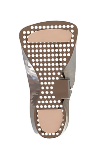
To allow for comfortable fit and viable housing for a sensor, an insole was designed bottom-up and fabricated using DLP 3D printing. Various cut-outs and slots were implemented into the design to allow for ideal placement of the sensors. Additionally, a 3D model of an existing insole shape was used to mimic the generic 3D shape of an insole, provided in collaboration with Dr. Colin Bradley.
Velostat based pressure-based sensors and an inertial measurement unit (IMU) were incorporated into the insole to record weight bearing, ankle flexion, extension, inversion, eversion and basic metrics in regards to a user’s stride.
Slots were included in the design to guide the cables which would insulate the conductive threading used as wires for the pressure pads.


Shank Strap
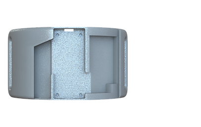
A shank strap was designed to house the microcontroller, force sensitive resistor (FSR), battery, IMU, effectively route wires, and to conform around the gastrocnemius to measure muscle activity with the use of a single FSR.
An FSR was installed to measure gastrocnemius muscle activity based on pressure applied to the sensor. In order to concentrate mechanical stress onto the FSR and maximise the readings, a small tab, shaped similarly to the FSR, was designed to overlay the sensor.
Additionally, the shank strap is responsible for housing one of two IMU sensors. By working with the IMU placed in the insole, the users ankle flexion/extension and inversion/eversion angles can be determined.
A cut-out is placed in the middle of the shank housing to contain an Adafruit Feather M0 microcontroller and an IMU sensor. A thin piece can be slid onto the top of the slot for the microcontroller to ensure adequate security. Next to the slot for the microcontroller is an additional slot for the routing wires into the main circuit. To power the system, a 3.7 V, 500 mAh lithium ion battery is used.
In regards to material, PLA was selected for the shank strap due to its light weight, low cost, and reproducibility using 3D printing. Additionally, PLA is tough and has a semi-porous surface from FDM printing, meaning it will bond well to other materials with glue. To bind the shank strap to a patient, a nylon strap with Velcro stitched on was used due to low cost and durability and a neoprene cover was used on the PLA.
Figure 1. DLP 3D-printed insole top side (left) and bottom side (right) with velostat pressure sensors
Figure 2. CAD Render of the shank strap
Figure 3. Shank strap cutout for MCU, battery, IMU and wiring
Wiring Diagrams

Figure 4. Shank strap wiring diagram

Figure 5. Insole wiring diagram
To visit our team website: